- 您现在的位置:买卖IC网 > Sheet目录474 > MAX66000K-000AA+ (Maxim Integrated)IC RFID UID 64BIT TYPE B KEY FOB
�� �
�
�ISO/IEC� 14443� Type� B-Compliant�
�64-Bit� UID�
�CID,� then� the� slave’s� response� also� includes� a� CID�
�MSb�
�LSb�
�byte.� Blocks� with� a� nonmatching� CIDs� are� ignored.�
�BIT� 8�
�1�
�BIT� 7�
�1�
�BIT� 6�
�BIT� 5�
�BIT� 4�
�CID�
�BIT� 3�
�0�
�BIT� 2�
�1�
�BIT� 1�
�0�
�According� to� the� standard,� the� slave� can� use� bits� 8� and�
�7� to� inform� the� master� whether� power-level� indication� is�
�supported,� and,� if� yes,� whether� sufficient� power� is� avail-�
�able� for� full� functionality.� Since� the� MAX66000� does� not�
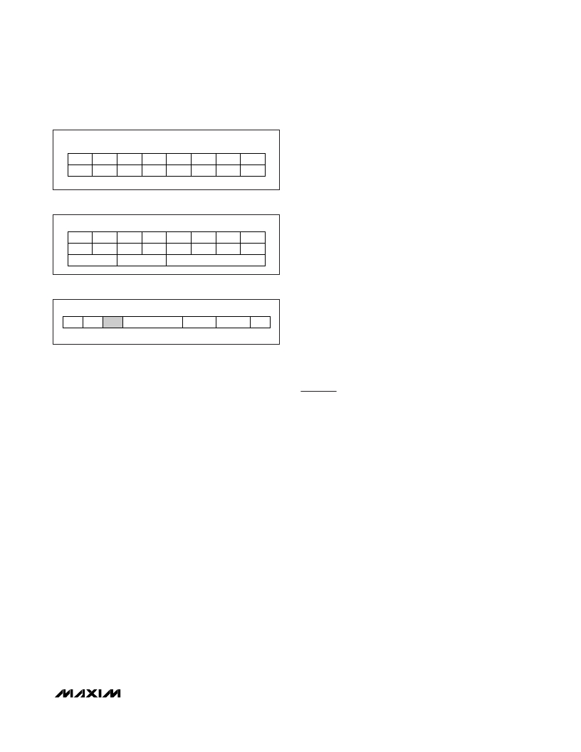
�Figure� 13.� Bit� Assignments� for� S-Block� PCB�
�MSb�
�LSb�
�support� power-level� indication,� the� power-level� bits� are�
�always� 00b.� When� the� master� transmits� a� CID� byte,� the�
�power-level� bits� must� be� 00b.�
�BIT� 8�
�BIT� 7�
�BIT� 6�
�BIT� 5�
�BIT� 4�
�BIT� 3�
�BIT� 2�
�BIT� 1�
�Information� Field�
�0�
�0�
�0�
�0�
�Since� the� MAX66000� does� not� generate� WTX� requests,�
�(POWER� LEVEL)�
�(FIXED)�
�CARD� IDENTIFIER� VALUE�
�the� information� field� (Figure� 10)� is� found� only� with� I-�
�blocks.� The� length� of� the� information� field� is� calculated�
�Figure� 14.� Bit� Assignments� for� CID� Byte� in� I-Blocks�
�by� counting� the� number� of� bytes� of� the� whole� block�
�minus� the� length� of� the� prologue� and� epilogue� field.�
�The� ISO/IEC� 14443� standard� does� not� define� any� rules�
�for� the� contents� of� the� information� field.� The� MAX66000�
�SOF�
�PCB�
�CID�
�INFORMATION� FIELD�
�CRC� (LSB)� CRC� (MSB)�
�EOF�
�assumes� that� the� first� byte� it� receives� in� the� information�
�field� is� a� command� code� followed� by� 0� or� more� com-�
�mand-specific� parameters.� When� responding� to� an�
�Figure� 15.� Frame� Format� for� Block� Transmission� Protocol�
�For� S-blocks,� the� states� of� bit� 1,� bit� 2,� bit� 3,� and� bit� 7�
�and� bit� 8� are� fixed� and� must� be� transmitted� as� shown� in�
�Figure� 13.� The� function� of� bit� 4� (CID� indicator)� is� the�
�same� as� for� I-blocks.� Bit� 5� and� bit� 6,� when� 00b,� specify�
�whether� the� S-block� represents� a� DESELECT� command.�
�If� bit� 5� and� bit� 6� are� 11b,� the� S-block� represents� a�
�frame-waiting� time� extension� (WTX)� request,� a� feature� to�
�tell� the� master� that� the� response� is� going� to� take� longer�
�than� specified� by� the� frame� waiting� time� (FWT)� (see� the�
�ATQB� Response� section).� However,� the� MAX66000�
�does� not� use� this� feature,� and,� consequently,� the� only�
�use� of� the� S-block� is� to� transition� the� device� from� the�
�ACTIVE� state� to� the� HALT� state� using� the� DESELECT�
�command� (see� the� Network� Function� Commands� section).�
�Card� Identifier�
�Figure� 14� shows� the� bit� assignment� within� the� card�
�identifier� byte.� The� purpose� of� bits� 4� to� 1� is� to� select�
�one� of� multiple� slave� devices� that� the� master� has� ele-�
�vated� to� the� ACTIVE� state.� The� CID� is� assigned� to� a�
�slave� through� Param� 4� of� the� ATTRIB� command� (see�
�the� Network� Function� Commands� section).� While� in� the�
�ACTIVE� state,� a� compliant� slave� only� processes� blocks�
�that� contain� a� matching� CID� and� blocks� without� a� CID� if�
�the� assigned� CID� is� all� zeros.� If� the� master� includes� a�
�I-block,� the� first� byte� of� the� information� field� indicates�
�success� (code� 00h)� followed� by� command-specific�
�data� or� failure� (code� 01h)� followed� by� one� error� code.�
�Memory� Function� Commands�
�The� commands� described� in� this� section� are� transmit-�
�ted� using� the� block� transmission� protocol.� The� data� of� a�
�block� (from� prologue� to� epilogue)� is� embedded�
�between� SOF� and� EOF,� as� shown� in� Figure� 15.� The� CID�
�field� (shaded)� is� optional.� If� the� request� contains� a� CID,�
�the� response� also� contains� a� CID.�
�The� command� descriptions� in� this� section� only� show�
�the� information� field� of� the� I-blocks� used� to� transmit�
�requests� and� responses.� Since� the� MAX66000� neither�
�supports� chaining� nor� generates� WTX� requests,� when� it�
�receives� an� I-block,� the� MAX66000� responds� with� an�
�I-block.� The� block� number� in� the� I-block� response� is� the�
�same� as� in� the� I-block� request.�
�Error� Indication�
�In� case� of� an� error,� the� response� to� a� request� begins�
�with� a� 01h� byte� followed� by� one� error� code.�
�If� there� was� no� error,� the� information� field� of� the�
�response� begins� with� 00h� followed� by� command-spe-�
�cific� data,� as� specified� in� the� detailed� command�
�description.� If� the� MAX66000� does� not� recognize� a�
�command,� it� does� not� generate� a� response.�
�_______________________________________________________________________________________�
�7�
�发布紧急采购,3分钟左右您将得到回复。
相关PDF资料
MAX66020K-000AA+
IC RFID UID 1KB TYPEB MEM KEYFOB
MAX66040K-000AA+
ISO CARD SECURE MEMORY
MAX6605MXK/V+T
IC TEMP SENSOR ANLG LP SC70-5
MAX6608IUK+T
IC TEMP SENSOR ANLG SOT23-5
MAX66100K-000AA+
IC RFID UID 64BIT TYPE B KEY FOB
MAX6611AUT+T
IC TEMP SENS LOW PWR SOT23-6
MAX66120K-000AA+
IC RFID UID 1KB TYPEB MEM KEYFOB
MAX6612MXK+T
IC TEMP SENSOR ANLG SC70-5
相关代理商/技术参数
MAX66000K-00AA+
制造商:Maxim Integrated Products 功能描述:ISO/IEC 14443 TYPE B-COMPLIANT 64-BIT, UID FOB - Rail/Tube
MAX66020K-000AA+
功能描述:RFID应答器 ISO/IEC 14443 Type B Comp 1Kb Mem Fob
RoHS:否 制造商:Murata 存储容量:512 bit 工作温度范围:- 40 C to + 85 C 安装风格:SMD/SMT 封装 / 箱体: 封装:Reel
MAX66020K-00AA+
制造商:Maxim Integrated Products 功能描述:ISO/IEC 14443 TYPE B-COMPLIANT 1KB MEMORY FOB - Rail/Tube
MAX6602UE9A+
功能描述:板上安装温度传感器 5Ch Precision Temperature Monitor RoHS:否 制造商:Omron Electronics 输出类型:Digital 配置: 准确性:+/- 1.5 C, +/- 3 C 温度阈值: 数字输出 - 总线接口:2-Wire, I2C, SMBus 电源电压-最大:5.5 V 电源电压-最小:4.5 V 最大工作温度:+ 50 C 最小工作温度:0 C 关闭: 安装风格: 封装 / 箱体: 设备功能:Temperature and Humidity Sensor
MAX6602UE9A+T
功能描述:板上安装温度传感器 5Ch Precision Temperature Monitor RoHS:否 制造商:Omron Electronics 输出类型:Digital 配置: 准确性:+/- 1.5 C, +/- 3 C 温度阈值: 数字输出 - 总线接口:2-Wire, I2C, SMBus 电源电压-最大:5.5 V 电源电压-最小:4.5 V 最大工作温度:+ 50 C 最小工作温度:0 C 关闭: 安装风格: 封装 / 箱体: 设备功能:Temperature and Humidity Sensor
MAX6603ATB
制造商:Maxim Integrated Products 功能描述:DUAL-CHANNEL PLATINUM RTD-TO-VOLTAG - Rail/Tube
MAX6603ATB+
制造商:Maxim Integrated Products 功能描述:RTD TO VOLT SGNL CONDITIONER 10TDFN EP - Rail/Tube
MAX6603ATB+T
功能描述:板上安装温度传感器 RTD-to-Voltage Signal Conditioner RoHS:否 制造商:Omron Electronics 输出类型:Digital 配置: 准确性:+/- 1.5 C, +/- 3 C 温度阈值: 数字输出 - 总线接口:2-Wire, I2C, SMBus 电源电压-最大:5.5 V 电源电压-最小:4.5 V 最大工作温度:+ 50 C 最小工作温度:0 C 关闭: 安装风格: 封装 / 箱体: 设备功能:Temperature and Humidity Sensor